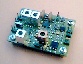
| SYMEK IFD-B-amplifier-mixer-demodulator board option 'IC821' | |
| wire and other hardware, connectors, heatshrink tube and other parts as needed. |
The IC821 can be simply modulated with up to 19200 Baud via ACC connector pin 4.
Note: To prevent overmodulation, the IC821 monitors the audio input voltage at pin 4. If there is excessive modulation voltage, the modulation is totally muted. So make sure not to apply too much voltage at pin 4. Reduce input voltage if there is no modulation when keying the transmitter!
Pin 3 of the ACC connector is used as PTT connection for keying the transmitter.
 3.
Demodulator output:
3.
Demodulator output:Open the top cover of the transceiver (front towards you). At the right, find the '430 MHz PA unit' and the loudspeaker. In the next compartment, there is the '70cm RF unit'. Carefully remove this printed circuit board from the case. The coax cables cannot be unplugged, so the board can be lifted only enough to access the SMD parts on the solder side.
Find the small (20x15mm) flat tin shield box on the underside of the 70cm RF unit. It is oriented towards the front of IC821. Compare the board with the picture below to find the capacitor C93, which couples the IF from the 1st mixer to the IF filter.
Remove C93 with extreme care. The tiny 0604 SMD capacitor is fixed with a heat resistant glue and needs some force to be removed. You should use a microscope for this.
 Prepare
two very thin ptfe coaxial cables (15cm each): remove cover insulation for 25
mm, the inner wire should be free from shield for 10 mm, the insulation of the
inner conductor is removed and the inner wire soldered and cut to 1 mm length.
Prepare
two very thin ptfe coaxial cables (15cm each): remove cover insulation for 25
mm, the inner wire should be free from shield for 10 mm, the insulation of the
inner conductor is removed and the inner wire soldered and cut to 1 mm length.
Now solder both cables to the pads, where C93 had been soldered before. For strain relief, solder the screens of the cables to a grounded pin (e.g. at L27). Make sure the shields do not touch any other point.
The 70cm RF unit may be re-installed now; the two cables will go through the gap between board and case (oriented towards front).
Schematics of 70cm RF unit.The arrow shows C93 (47 pF) which is removed to insert the IFD. The 430 MHz signal comes from the right, is converted (Q14/Q15) and goes to the filters at left.
Use a ohmmeter: the cable going to the mixer output has zero W resistance to ground, the other (going to the crystal filter) has 2.2 kW to ground. The mixer output goes to RF IN of the IFD, the cable going to the crystal filters is connected to RF OUT.
Ground connection for power supply is not necessary (cable shields are already grounded).
Find a point with permanent 12 Volt supply and connect it to the +12V pin of IFD. Simply find the red and black wire at the main dc switch.
Pin 8 (center pin) of the ACC connector is used for ALC voltage. As this feature is normally not used, pin 8 can be disconnected from the printed circuit board (pinch the metal connection at the rear side of the connector). Solder a (shielded) wire from ACC pin 8 to the data output of the IFD.
You need a 3 wire + screen cable from the IC821 to the packet controller. When using the ACC connector as described above, you only need an apropriate cable between the ACC connector and TNC:
Pin 2 Ground (connect to TNC pin 2 GND
Pin 3: PTT (connect to TNC pin 3: PTT)
Pin 4: Modulation (connect to TNC pin 1: Mod)
Pin 7: 12,5 Volt supply (not used)
Pin 8: originally used as ALC output. Now used for data output (connect to TNC pin 4: Demod)
After reinstalling all covers, the transceiver should work exactly as before. Because of the additional IF amplifier, the s-meter may show few dB increase.
Adjust the output level of the TNC to get the desired frequency deviation / modulation index. Do not overmodulate as the transceiver will totally switch off the modulator. The modulator should work perfectly for all FSK baudrates from 9600 to 76800 baud. Note: the input voltage determines the bandwidth of the transmit signal. You will need more signal amplitude for higher baudrates.
The RSSI output should be near zero volts (<0.1 m V signal) and go up to 4 volts (1 mV rf input)
When receiving a 19200, 38400 or 76800 baud signal, there will be a perfect eye at the data output. The output voltage at 38400 Baud is typically 0.5 volt pp.
The IC821 uses two different IF Frequencies (71.250 and 71.350 MHz). If IFD operates at 71.35 MHZ, the displayed RX frequency is only correct if the 71.35 MHz IF is selected. This is true for satellite-mode (RX 70cm TX 2m) or split mode (RX 70cm TX 2m). With the other modes (satellite RX 2m, TX 70cm, split mode RX 2m TX 70cm and 70cm monoband mode), the displayed frequency is 100 kHz below the frequency received with the IFD. For those modes, set the RX frequency 100 kHz higher.
"DISCLAIMER: These instructions worked for me. Try them at your own risk. I am not responsible for *anything* that happens to *any* radio equipment you own (or might ever own) by following these instructions. READ ALL THE INSTRUCTIONS THAT CAME WITH THE BOARD!
Whew, my trials and tribulations since entering the amateur satellite realm compound... ;-) .
Bought a Symek IFD and TNC31S last week to install in my IC-821. I got the equipment on Tuesday and have been installing it ever since. However, I finally got it working last night. Here's the story:
First, I am not an "experienced" experimenter or kit-builder. This is the first thing I've tried to tackle since I graduated electronics school and SatCom school at Keesler AFB in 1992. The first day of installation was frustratingly slow (I'm not a patient person by nature, but I was trying very hard this day as I had a $1500 piece of electronics that I didn't want to turn into a $1500 "lump" of electronics).
I read the instructions as best I could (the instructions are *excellent*) and re-read and re-re-read. MAKE SURE YOU LOCATE A LIT MAGNIFYING GLASS LIKE JEWELERS USE FOR MINUTE WORK! I finally started to work on the radio. I first removed C93 which apparently, in this day and age of SMD, is not labeled. As luck would have it, Symek has, again, done an excellent job describing its location. BTW, the instructions say that the coax on the 70cm board cannot be removed. Icom must have made a change, because mine were easily removed giving easy access to the bottom of the board. Also, C93 didn't appear to be held in place by any sort of heat-resistant glue.
I then prepaired the ptfe coax. I cut them to 15cm each (Symek says these lengths aren't critical, but you want some slack to connect to the IFD board). Strip 25mm off each end of the ptfe, then trim the shield back at least 10mm. I used a small jeweler's screwdriver and meticulously unwrapped each individual shield wrap down to the outside insulation that is remaining. I carefully stripped back about 3mm (about 5mm on the side to the IFD) of the dielectric and tinned both the center conductor and shield. (Note: you may tin the complete outer conductor with lots of heat and solder first. Then make a notch around and bent the tinned mesh until it breaks along the notch. PTFE doesn't melt. This is the only reason why we prefer ptfe instead of polyethylene.) Prepare both ends of both cables before you go any further with anything. Doing this small work using the jeweler's magnifying glass, I had to get up and walk around for a while after preparing each end due to eye strain. Once the coax is prepared, you're ready to install them in place of C93.
Follow the instructions verbatim for this. Trim the shield short enough that it doesn't come in contact with anything - I trimmed each to about the lengt of wire sticking out of the solder pad and soldered in place. Check your grounds with an ohmmeter.
Once you are done with the RF board portion of the installation, you can replace it taking care not to break your solder connections you just made. Again, check with an ohmmeter to make sure you haven't shorted or opened anything. Now you are ready for soldering to the IFD board. I recommend that you mount the IFD board in your transceiver before doing this. I mounted mine using the dual-sided sticky pads that come with telephone jacks. I used two because the wires stuck thru from the solder pads on the first sticky pad. With the front of the radio facing you and the top facing up, there is a blank spot just below and to the right of the RF board (it is right behind the front panel). I mounted my IFD board vertically there. It will be just in front of the PA fan and to the left of it. Start your solder connections to the IFD board. The instructions include a layout diagram of the board. The RF-IN, RF-OUT, DATA-OUT are labeled around the board in the diagram; all these connections are the *outside* pins. The inside pins are all ground. Ground your RF-IN and RF-OUT. I tried grounding DATA-OUT and I got noise in my rcv when I turned the tuning dial; however, this was done in an effort to provide a return for the IFD board and was before I grounded the RF-IN and RF-OUT. Don't let that last statement confuse you, just don't connect the shield from your DATA-OUT connection. I got 12VDC from the front panel. If you look at the front panel circuit board on the left, you'll see a red wire and a black wire. These come from the main power switch. Solder a wire to the 12V wire (mine was red) and solder the other end to the 12V on the IFD board. Use tie-wraps to secure.
The last connection was to pin 8 of the ACC connector. Follow the instructions for this. I actually used a piece of RG-58 for this as I was out of ptfe coax. (Note: any other shielded wire will do as well.) I stripped back enough insulation and did the shield as I mentioned above. Tin the sheild and heat-shrink it. I put a DC lug (put it on *before* the heat-shrink) on it and connected to the chassis screw just to the left of the ACC connector with the radio's bottom facing up and the front facing you. Route your coax in such a way as it will not interfere with replacement of the bottom cover. At the IFD end of this coax, strip back the insulation (about 40mm) and cut the shield off. Connect the center conductor to the DATA-OUT connection and cover with heat shrink.
That's it! Replace all your covers and try
your radio out. If everything is working, you should be able to hear local
repeaters and the satellites as they pass overhead.
GL es 73, Joel B. Black, K2SAT"
![]()
"Later comments: Wow! What speed! Finally got my system up and working for UO-36.
Copied during the 1654U pass. Saw W0SL and W4SM on there too.
I first started at a downlink of 437.025+/-10kHz. This didn't work, but it took me half the pass to realize there was another downlink. I went to 437.400 and there was the downlink. In about 4 minutes, I copied 235810 bytes with 0 overrun errors and 0 CRC errors. I copied at 76% efficiency. Didn't get a single file, but at least now, I know my setup works. Can't wait for the 1837 pass.
Tnx to all who helped with this. Instrumental to my success were Stacey Mills, W4SM; John Melton, N6LYT/G0ORX; and Ulf Kumm, DK9SJ. Looking forward to the next pass. Joel B. Black, K2SAT"
![]()
"Dear Ulf , I install on my IC820H the Symek IFD module: the most difficult is to remove the MSC condensator. I work's fine the first time without any modification! Today I download about one MByte from UO-36 (38.4K ) in a pass only 20° above the horizon! Very nice : =)) best 73 from Tahiti, French Polynesia. Yves FO3PJ"
![]()
"I can confirm you that the mod i buy for ICOM 821H works good olso on the 820H. Yesterday i make it work and at the first pass the wisp start to receive files from the satellit. Is nice to see how fast goes. 73 de IZ3ALU, Walter Cortina d'Ampezzo, Italy"